[help needed!] KORG V-C-F FK-1 Traveler filter (aka Univox Korg Synthepedal)
Posted: Sun Aug 20, 2023 9:59 pm
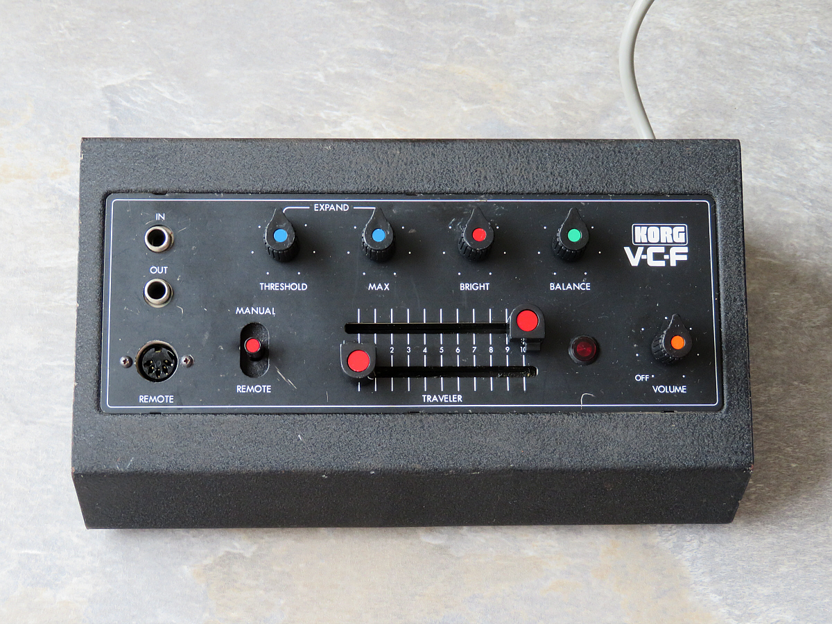
In early July I purchased a very rare KORG V-C-F filter unit (without the accompanying pedal for the Remote jack). Somehow it got lost in the mail and after a very crazy and nerve-stretching odyssey with the German post service the quite beat-up parcel finally arrived in early August.
At first the V-C-F didn’t work and I suspected the blown fuse as the main culprit. I was right! When I replaced it the unit was alive again. Only the pilot lamp is still faulty.
The sound of the filter, however, is not how it is supposed to be. I have an original KORG 800DV duophonic synthesizer that contains a pair of this same highpass/lowpass filter combination, so I know how the sound should really be. The lowpass filter is set way too high, so everything sounds very thin.
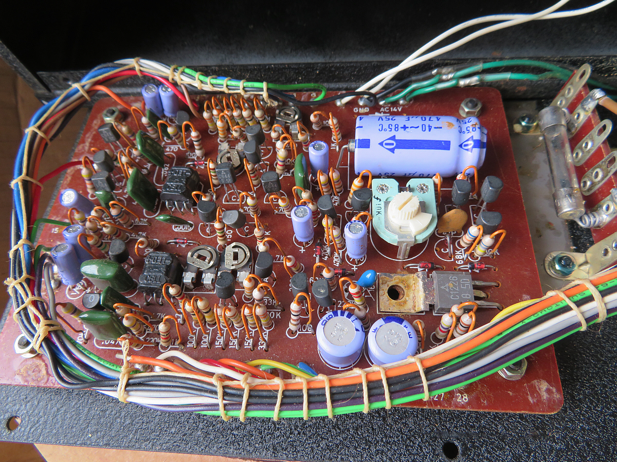
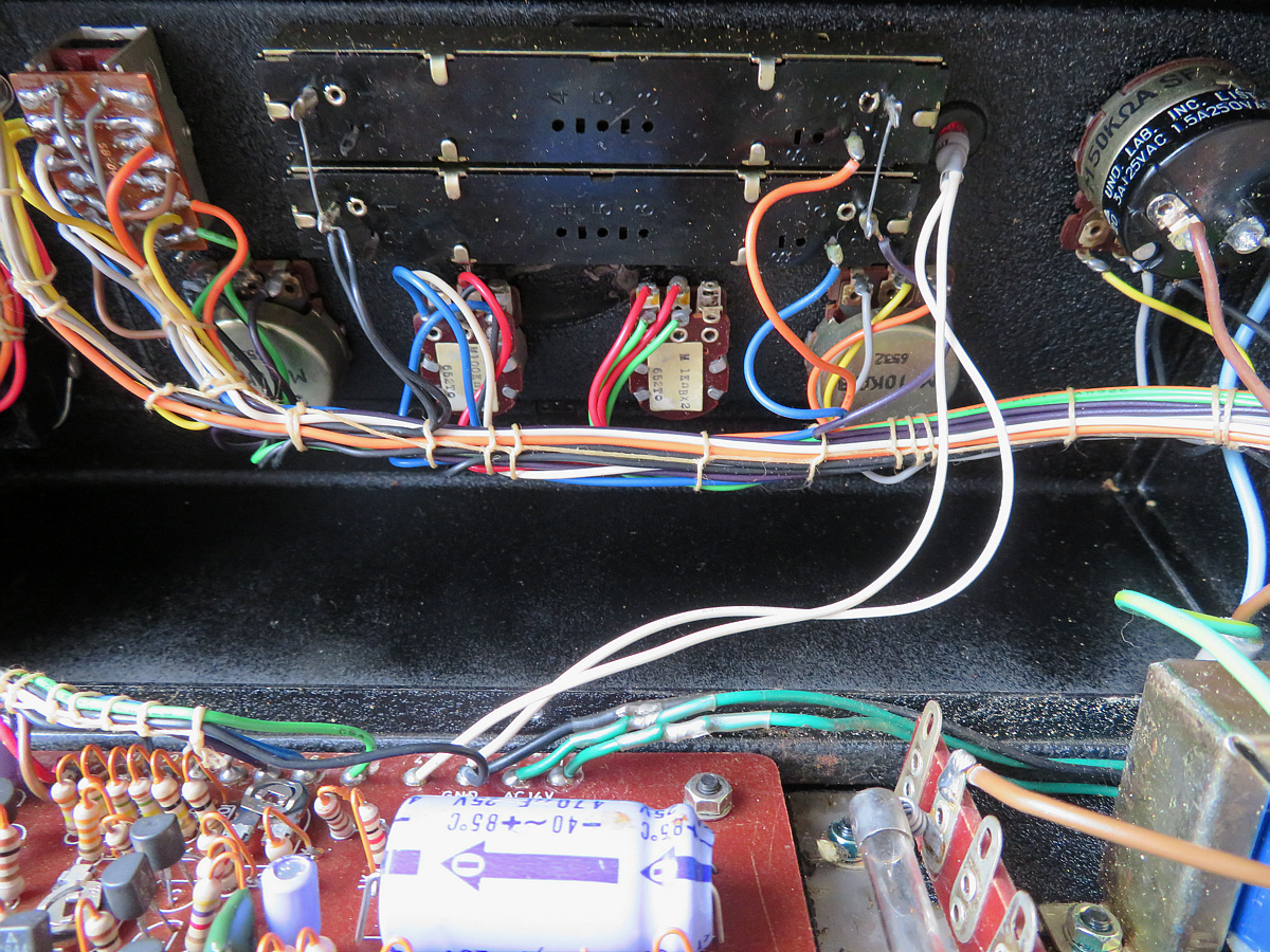
In the meantime I did a full recap with high quality electrolytic capacitors, but that didn’t change the overall sound. (The pictures below were done before the recapping.)
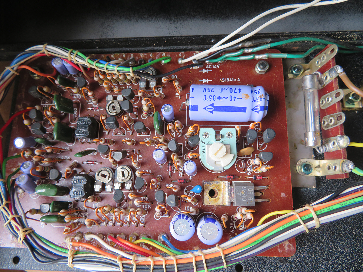
I suppose that the previous owner fiddled around with the trimpots for whatever reason after the fuse was blown. Now I would like to know what the five trimpots are exactly doing. Thanks a ton in advance for any help!
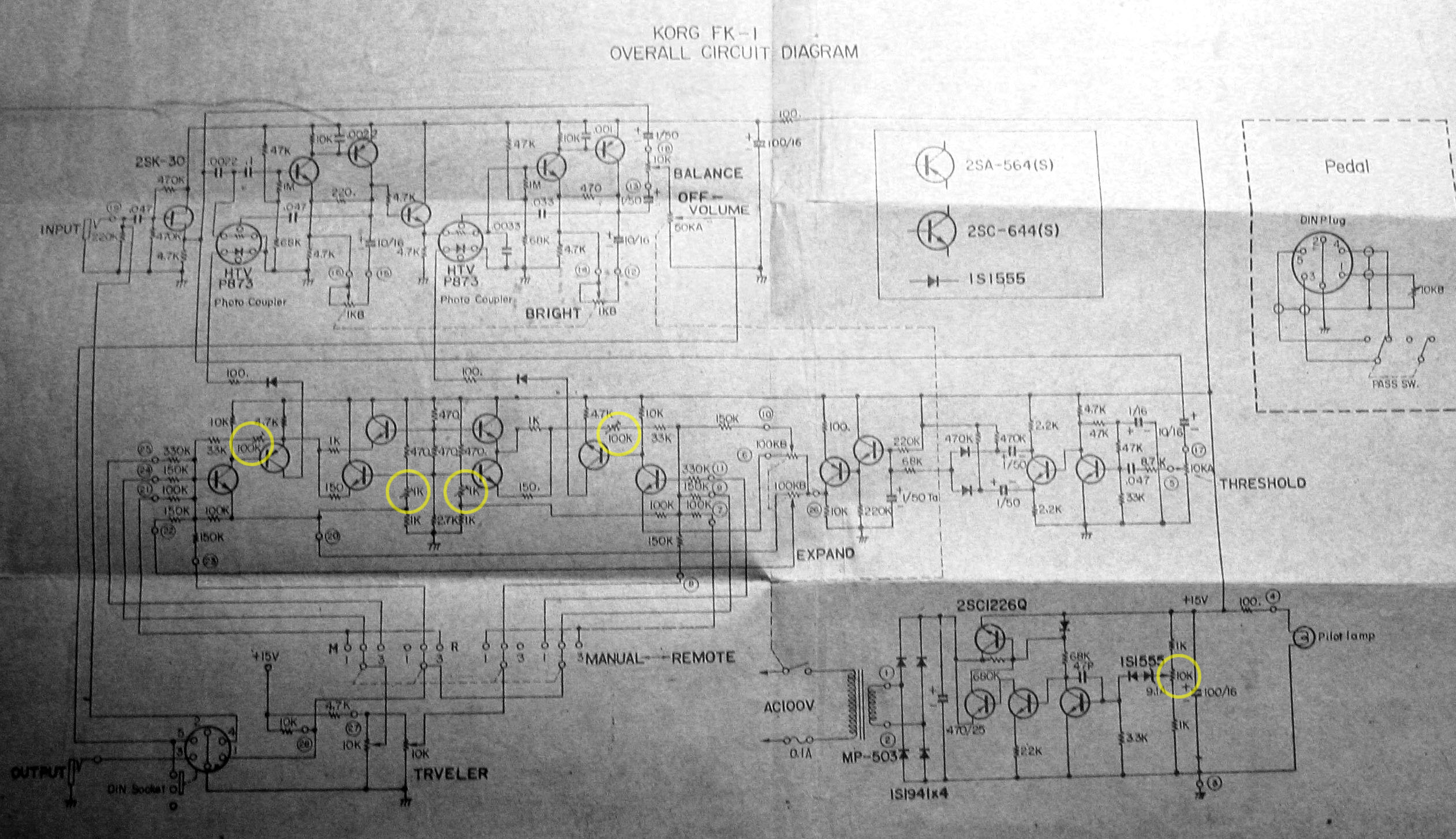
There is no service manual around, in the internet only this same lo-fi photograph of the schematics can be found, so I share it here:
KORG V-C-F schematics
We have a 10 kOhm trimpot that seems to adjust the main voltage for the circuit. This one is quite big and can be turned with bare fingers. It might look very inviting touching this one if you have absolutely no idea what you are doing, so I guess this could very well be the one that the previous owner has fiddled around with.
And then there are each two trimpots in the circuit path after the 10 kOhm slider potentiometers of the highpass and lowpass ("Traveler") filters. I can only guess that these 100 kOhm trimpots define the right frequency for each filter, but what do the two 1 kOhm trimpots do? Do these define the intensity of the "Expand" function?
At first the V-C-F didn’t work and I suspected the blown fuse as the main culprit. I was right! When I replaced it the unit was alive again. Only the pilot lamp is still faulty.
The sound of the filter, however, is not how it is supposed to be. I have an original KORG 800DV duophonic synthesizer that contains a pair of this same highpass/lowpass filter combination, so I know how the sound should really be. The lowpass filter is set way too high, so everything sounds very thin.
In the meantime I did a full recap with high quality electrolytic capacitors, but that didn’t change the overall sound. (The pictures below were done before the recapping.)
I suppose that the previous owner fiddled around with the trimpots for whatever reason after the fuse was blown. Now I would like to know what the five trimpots are exactly doing. Thanks a ton in advance for any help!
There is no service manual around, in the internet only this same lo-fi photograph of the schematics can be found, so I share it here:
KORG V-C-F schematics
We have a 10 kOhm trimpot that seems to adjust the main voltage for the circuit. This one is quite big and can be turned with bare fingers. It might look very inviting touching this one if you have absolutely no idea what you are doing, so I guess this could very well be the one that the previous owner has fiddled around with.
And then there are each two trimpots in the circuit path after the 10 kOhm slider potentiometers of the highpass and lowpass ("Traveler") filters. I can only guess that these 100 kOhm trimpots define the right frequency for each filter, but what do the two 1 kOhm trimpots do? Do these define the intensity of the "Expand" function?